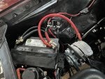
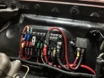
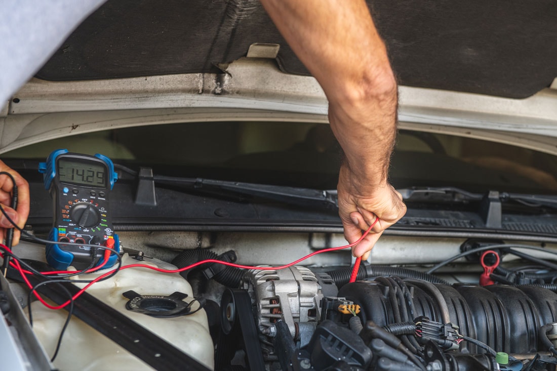
Ford Muscle Cars Tech Forum banner
21 - 40 of 82 Posts
Please review the output data for the alternator of your choice, to see if it will do the job. While you're at it, look at a few others for options. For example, the Ford 3G alternator is popular, as it charges with more amps at idle speeds, for the same general "rated amps". If an alternator makes 100A, but it's at 3000 rpm, that isn't helping your low-speed operation.

As to volts > amps, or torque > HP, they are inseparable but different perspectives of what's happening. You can't have enough volts if your amps are too low, and vice-versa. Ohm's Law. While insufficient amps is the problem, you see it as low voltage. Likewise, you can't pump more amps through if you don't have the volts to push it. This isn't an either/or situation, and can be calculated for specific answers, if that's what you're after. 🤷‍♂️

Note both charts are in alternator shaft rpm, not engine rpm. Calculate your pulley ratio to find amps at your idle rpm. These are typical of GM 10si or 12si type alternators. Note the output leads on the 55, and at 2000 shaft rpm are crossing:
Image


Here are several Ford types that use different construction. Note the output at the same 2000 shaft rpm for each rating:
Image
 
Discussion starter · #23 ·
Please review the output data for the alternator of your choice, to see if it will do the job. While you're at it, look at a few others for options. For example, the Ford 3G alternator is popular, as it charges with more amps at idle speeds, for the same general "rated amps". If an alternator makes 100A, but it's at 3000 rpm, that isn't helping your low-speed operation.

As to volts > amps, or torque > HP, they are inseparable but different perspectives of what's happening. You can't have enough volts if your amps are too low, and vice-versa. Ohm's Law. While insufficient amps is the problem, you see it as low voltage. Likewise, you can't pump more amps through if you don't have the volts to push it. This isn't an either/or situation, and can be calculated for specific answers, if that's what you're after. 🤷‍♂️

Note both charts are in alternator shaft rpm, not engine rpm. Calculate your pulley ratio to find amps at your idle rpm. These are typical of GM 10si or 12si type alternators. Note the output leads on the 55, and at 2000 shaft rpm are crossing:
View attachment 186397

Here are several Ford types that use different construction. Note the output at the same 2000 shaft rpm for each rating:
Image
Thank you for the information! I am definitely learning alot about Alternators!
I have been seeing Ford 3G’s in other forum Alt conversations and was gonna ask about them. I am probably going to go that route, but will make sure to research the tech sheet data for sure before I make a final purchase.
 
This is what I run on my 390

Tuff Stuff 3g Alt - 150A

It's not a daily driver but I do run the following (almost NEVER all at once:

Halogen headlamps (thru relays)
Heater motor
Dual Derale cooling fans
"Modernized" stock radio with bluetooth (built-in amp, but not powerful at all)
MSD ignition
Convertible top

Overkill? Probably. But I do plan on running a "real stereo" in it one day. It did have to be re-clocked, but that's easy to do.
 
  • Like
Reactions: Smak_Davis
BTW, while the alternator only makes the amps required under specific conditions, the system must be able to handle those amps in-case it ever does. So, a huge alternator will only squeak 17A if that's all that is required right now, but if you have a dead battery in a parking lot and get a jump, the entire system, drive and cabling must be up to the huge amps it will blast on start-up. Just sayin' the right capacity is optimal, bigger isn't always better, and can be much more work and expense if you won't actually need it. 🤷‍♂️ Have fun!
 
BTW, while the alternator only makes the amps required under specific conditions, the system must be able to handle those amps in-case it ever does. So, a huge alternator will only squeak 17A if that's all that is required right now, but if you have a dead battery in a parking lot and get a jump, the entire system, drive and cabling must be up to the huge amps it will blast on start-up. Just sayin' the right capacity is optimal, bigger isn't always better, and can be much more work and expense if you won't actually need it. 🤷‍♂️ Have fun!
What's the point of this? Genuine question, not trying to be a jerk. "Have fun" isn't exactly instructive. So what information should be taken from this post in preparation for installing a larger alternator in a car that likely WILL need it? Yes, good connections, proper gauge wiring, GOOD battery cables and good grounds? What else are you suggesting?
 
That is all I am suggesting. Suggested is to measure or calculate the capacity you need, and then buy the capacity you need, and configure the entire system to handle that capacity. Or, buy more than you need, but you then have to increase handling further for whatever it could make. I mentioned all of this, as it is very common to find owners dropping a larger-capacity alternator in with no matching improvements to handle the capacity. A good way to have future issues.

"Have fun!" is just that – enjoy the experience and making informed decisions that will serve you well, or at least better than guessing. Did you think there was or should be some other points included? I'm happy to add anything overlooked.🤷‍♂️
 
Let's try all of this again ...

FACTOID NO. 1) - THE GM-DELCO ONE WIRE ALT was designed and released for farm tractors.


FACTOID NO. 2) - The sight of a DELCO ALT INSTALL (along with a matching HEI CHI-CON SLOPPY COPY DIST) makes me cringe.

All the man was trying to convey is that if one is going to upgrade an ALT (either GEN CONV or to a higher AMP), it requires much more than bolting one on and going down the road.


I think the newer 3g alternators operate well even at idle speeds. If he does want to speed up the alt at idle it may require a smaller alt pulley. Larger crank pulley will likely hit the water pump pulley. They are close!
 
Discussion starter · #32 ·
So I have been a busy bee on this ol girl and I believe I have rectified most if not all of my issues.
as mentioned in a previous post in here I had already done the big 3 upgrade. Which is 1/0 gauge wire coming off of battery negative to frame, engine to frame ground, positive from alternator to Battery, and for added measure grounding the alt to frame.
I also upgraded the engine to firewall ground.
I purchased a fuse block with a negative bus and 2 positive buses. (One for constant power and one for switched power).
I also purchased a 75amp relay to power the switched side of the positive bus. This relay is powered from the positive feed that goes out to the HEI distributor.
I then re-wired all of the accessories to the new fuse block. (Aftermarket gauges, amplifier, tachometer, electric choke,) Each now has its own positive and negative spot on the buses.
I removed the positive feed that goes to the dash and to the ignition, from off of the starter relay and placed it on the constant bus with a 30amp fuse.
I also wired in 2 relays for the headlights for Hi and Low beam.

I got it all together, and tested as I went. And I went to start the car and I turn the ignition to On position and everything works, even turn it to accessories and everything I turn on operated as beautifully. I turned the key to the start position and it sounds like an air hammer, and I see sparks at the negative battery terminal😳.
So that lead me to a frantic check and troubleshoot and recheck and draw schematic and through the tornado of checking everything it came to be that the original starter failed and was causing the starter relay/solenoid to make that air hammer sound.
NOW, I have a NEW starter and solenoid/relay and the car started up with no issues and the voltage is staying SOLID at 14 volts. With Everything on! Amp, wipers, headlights, blower of high, and while Idling!! I still have the same alternator which is like 65-68 amps.
The car seems to run better and respond better as well!!
I think the only thing that I’m going to add onto this at the moment is another relay that will be tied into the feed to the HEI distributor.
But for now I am gonna save up for an upgraded Alternator and call this one GOOD💪🏼
 

Attachments

Which is 1/0 gauge wire coming off of battery negative to frame, engine to frame ground, positive from alternator to Battery, and for added measure grounding the alt to frame.
Lots of progress! (y) As your cabling is fresh, it should be fine. If I'm following your description, the primary battery(-) post cable should go to the engine block, typically to the starter mount, or to a collective stud near the front of the block.

An additional lighter cable then runs from the block to the frame, and block to firewall. The purpose here is to provide minimum connections and lowest resistance from the battery(-) to the starter, ignition, sensors, and alternator grounds through the block. Frame (chassis) is secondary at much lower amps for lighting, radio, wipers, etc. Hope that helps for best results!
 
In your future research on larger alternators I would consider the 130A, Ford 3G. I have used that on three cars so far with very good results. It also simplifies the wiring by removing the separate voltage regulator. All had AC and electric fuel pumps. One had a larger sound system and electric Cooling fan. My current build also has the 3G but it is not on the road yet.
 
Smak_Davis,

Congrats on solving your issue and thanks a lot for taking the time to explain and post pics; I’m also planning to do the ‘Big 3’ upgrade.

An additional lighter cable then runs from the block to the frame, and block to firewall.
PSIG, do I understand you correctly in that a 1/0 ground wire in these types of applications would not be a benefit, and can possibly be counter productive?

Thanks!
Terry
 
No problem with a bigger primary (or any) cable, as it can reduce resistance and voltage drop in the system, for greater accuracy and reliability. That said, it's not necessary (except sized to handle max potential amps) but no harm otherwise. Enough is enough. I have also run a 1/0 on the primary cables for a high-demand vehicle setup without issues.

This does not exempt using a voltage sensing (yellow) wire for 3G alternators, or the same wire type for externally-regulated alternators. That sensing wire is very important for stable regulation (to everything) and proper battery charging, and one reason 1-wire alternators or jumping the sense wire to the alt BAT terminal are not suggested.

"Lighter" only means enough gauge to handle the chassis loads that you already know exist, but connected in the order that favors minimum connections and voltage drop to the most important devices, such as starter, sensors, ignition and alternator. The chassis stuff like lights and wipers join to that as a secondary priority. The engine is always the primary collector of all grounds routing to the battery(-). (y) The chassis/ frame and body are secondary, but also tie to the block as the final collection point to route to the battery(-).
 
Discussion starter · #39 ·
Lots of progress! (y) As your cabling is fresh, it should be fine. If I'm following your description, the primary battery(-) post cable should go to the engine block, typically to the starter mount, or to a collective stud near the front of the block.

An additional lighter cable then runs from the block to the frame, and block to firewall. The purpose here is to provide minimum connections and lowest resistance from the battery(-) to the starter, ignition, sensors, and alternator grounds through the block. Frame (chassis) is secondary at much lower amps for lighting, radio, wipers, etc. Hope that helps for best results!
Im glad you brought this up and made me double check and get it right! I had the battery ground originally going to the previous owner location which was this bolt.
Image

this bolt is holding an old cast iron generator bracket. And Thats when I was getting the starter relay woodpecker noise.
Image


So I moved the battery negative to a clean spot on the frame crossmember and still used that bolt for (engine to frame ground) And that seemed to work well enough, but I wasnt comfortable with it, and There were a couple times in the past day or so where it seemed a touch hesitant to start. I could already see some corrosion wanting to form on the neg battery post in just a couple days.
After reading your comment I have now changed it again and it should be correct.
I have a 1/0 guage from battery neg to front of engine block. I found a spot right above the oil pan. An open 7/16 x14 thread hole. And from that spot I also attached a 4 gauge wire that now goes to the crossmember frame spot.
Image

Now it fires up with no issues. Turn the key and Bang!!
 
Discussion starter · #40 ·
While replacing the alternator, i would really like to replace the alt bracket. Reminder this is a 302 with AC and power steering pump (reservoir is on the firewall) is on driver side.

What type of bracket do you all recommend?
I have seen many different styles.

Right now I am using the old generator bracket that I chopped and modified to fit the alternator better. But its big, heavy, ugly and its time to go.
From some research it appears a couple things matter, like water pump housing, factory AC or not, power steering pump and things like that. So Im a little confused on what to get.
Any assistance or guidance would be greatly appreciated🤘🏼.
 
21 - 40 of 82 Posts